Posts

Showing posts from December, 2019

Handover Decision

Image
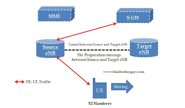
Home                 LTE                NB-IoT            5G(NR-NSA)   Handover Decision: As soon as the event A3(for instance) is reported the eNB decides what kind of handover to perform to which target cell and then initiates a handover procedure. Handovers can be classified in many ways one of the classification is as below – (1) Depending on weather EPC Entities that UE is connected to are changed after a handover or not a handover can be categorized as one of the following kinds: (Interview Question: What are the types Handover?)   Intra LTE handover – Intra MME/SGW handover – Neither UE’s serving MME nor SGW is changed after handover. Inter LTE handover -  UE’s serving MME and/or SGW is changed after handover Inter MME HO: UE’s serving MME is changed, SGW remains unchanged after handover. Inter SGW handover: UE’s MME is unchanged, SGW is changed after handover. Inter MME/SGW Handover: Both MME and SGW are changed after handover. Inter

SSB Part-2

Image
Home                 LTE                NB-IoT                  5G(NR-NSA)   5G synchronization process: In a specific protocol stack implementation, the frequency and time synchronization of the first step can be implemented in a process that is followed by the decoding process of the subsequent PSS and SSS. For example, a possible implementation process can be explained as below: First of all the terminal tunes the RF receiver to a designated frequency point. Perform cross-correlation detection on the PSS in the time domain to get time domain synchronization and obtain the cell ID (NID2). In the first symbol time of the SSB, only the PSS signal is in the SSB frequency domain, so it can be correlated. On the contrary, because there is a PBCH in the third symbol time of the SSS, it is impossible to perform time domain correlation detection on it, see below Figure: As per, the location of the PSS, the location of the SSS can be obtained, and the cross-cor

Synchronization Signal Block

Image
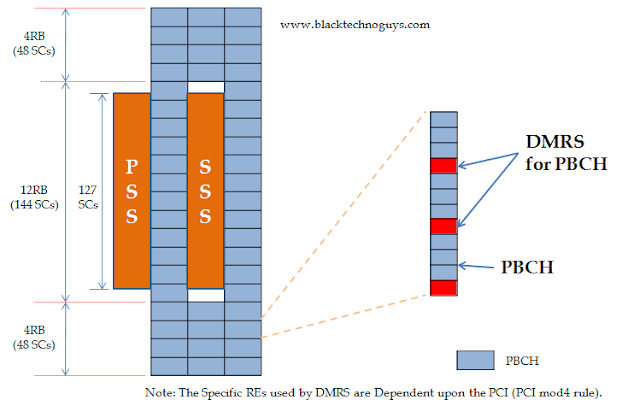
Home                 LTE                NB-IoT                  5G(NR-NSA)   The SS Block or SSB refers to the synchronization signal block, which actually refers to the synchronization or PBCH block as the synchronization signal and the PBCH channel are always packaged together.  The SSB is a key part of beam management. To enable device to find a cell while entering a system, as well as to find new cells when moving within the system a synchronization signal consisting of PSS and SSS is periodically transmitted on the downlink from each NR cell.  Thus PSS, SSS along with PBCH can jointly be referred as SS Block. Thus we can say that SSB consists(4 OFDM symbols) of following parts: Primary synchronization signal (PSS) (127 Subcarriers) (1st OFDM symbol out of 4 OFDM symbols) Secondary synchronization signal (SSS) (127 Subcarriers) ( 3st OFDM symbol out of 4 OFDM symbols) Physical broadcast channel (PBCH) ( 2nd,3rd and 4th OFDM symbols)

Carrier Aggregation Part-3

Home                 LTE                NB-IoT            5G(NR-NSA)   Which layer impact using CA? CA mandatory requirements impact RRC, MAC, and PHY layer procedures. Which layer does not impact using CA? Carrier aggregation does not impact the RLC/PDCP/NAS procedures and protocols. Does CA activate in RRC idle mode? There is no carrier aggregation for the UE in RRC Idle mode. Is there any a change or impact in Camping process due to CA? No, there is no change in camping process due to CA because CA will activate in connected mode only. Is there any a change or impact in idle mode due to CA? No, there is no change in idle mode due to CA because CA will activate in connected mode only. Is there any a change or impact in registration due to CA? No, there is no change in registration due to CA because CA will activate in connected mode only. Does SRB(signaling radio bearer) establish for Scell? SRB is not established between the UE and

Measurement in LTE

Image
Home                 LTE                NB-IoT            5G(NR-NSA)   What is Measurement? Measurement configuration and measurement report are used by UE while measuring and reporting the strength of signals that it receives from cells. Below figure illustrates the same. Measurement configuration: (What does measurement Configuration indicates?) The measurement configuration indicates what measurement information needs to be reported and is provided by eNB to UE. This measurement configuration is provided by eNB to UE through RRC connection Reconfiguration message when it establishes an RRC connection with the UE. Measurements could be interfrequency, intrafrequency or IRAT (intersystem). UE can get the following information a measurement configuration includes: Measurement Objects, Measurement Identities, Reporting Configurations, Quantity Configurations and Measurement Gap Configurations: 1) Measurement object: The objects provides inform